On one happy day Santa Claus came into my home and brought me some parts to make the Tricopter 🙂
Since I saw detailed build log of David’s Tricopter I started to think about having one:-) Not about quadcopter, hexacopter of other kind of -copter, but it had to be folding tricopter. Meantime I collected few useful small and handy parts, so only most impotant (and costly) parts left to buy. And now arrived: motors, ESCs, props and servos (but in buget version).
So, let’s start building 🙂
Update 2013.06.10: I made some errors and bad decisions during this build, please read short summary before you follow this build log.
Tail servo
At the beginning look at my new servo: HK15148B Digital Servo.
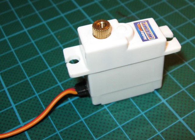
I hope that it’s not too weak, because David used stronger one.
Looks nice, but if you looked at Rcexplorer’s build log, you should notice that this servo should lay on it’s left side. And there is a first problem: on the left side there is a cable output.
So let’s look what we can do with it:
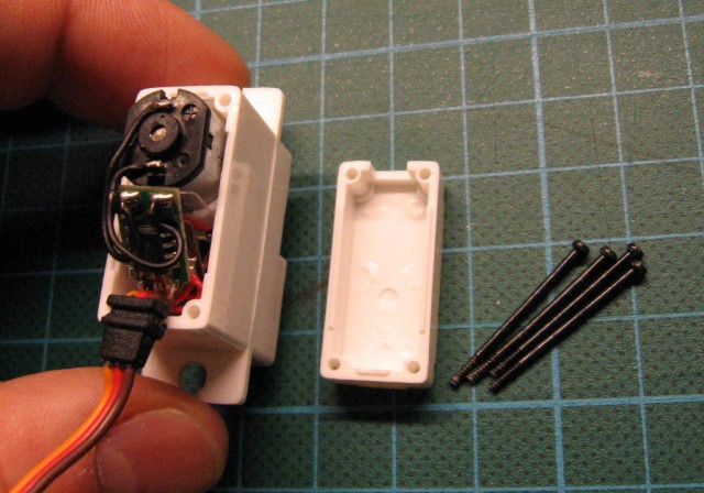
Looks promising 🙂
I made a hole on bottom part of servo for new cable output:
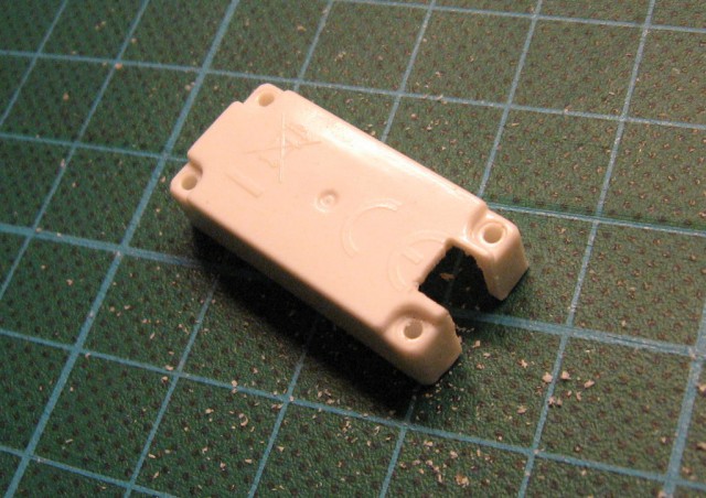
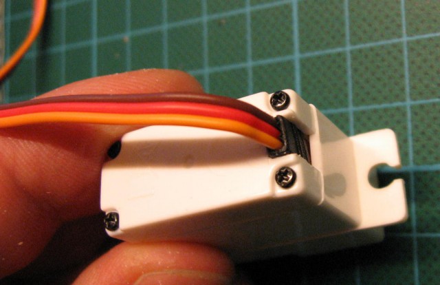
bend cable to the bottom of servo and assembled it that way.
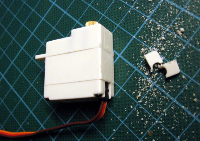
Cut handle and servo is ready:
Yaw mechanism/cradle.
Servo should sway tail motor to make yaw work.
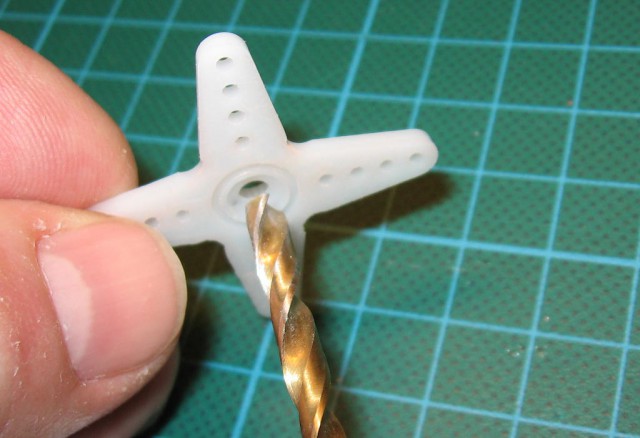
I got one X servo’s arm and increase inner hole to 4mm:
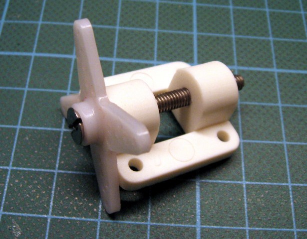
Now I could put a M4 screw through servo arm and one piece of wheel mount and glue it together using epoxy. Of course before glueing I sanded both adjoining surfaces. Trick with screw is for centering both pieces.
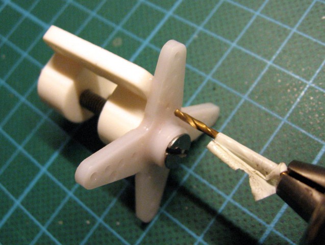
After epoxy cured, I drilled 1.5mm holes for small screws (probably I have it from other HXT micro servos). Next, I increased holes only in arm part to 2mm (by drilling 🙂 ).
Next step was to cut excessive parts and one part of sway mechanism is ready:
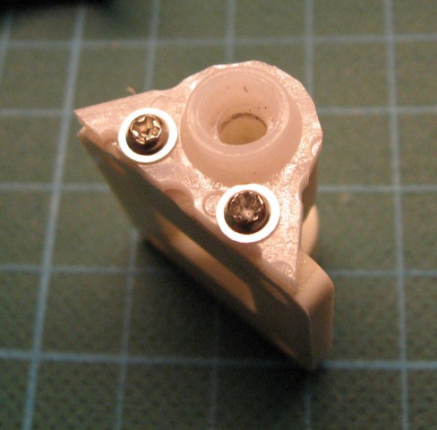
I decided to make this part a little other way than in original Tri because I didn’t have 4mm carbon fiber rod. Hole in part of wheel mount is about 3.95mm, so I drilled it once again using stock 4mm drill (only part connected with servo arm!), so screw inside this part will be a little more loose. Having weight in my mind, I replaced steel screw with nylon one and put two parts together:
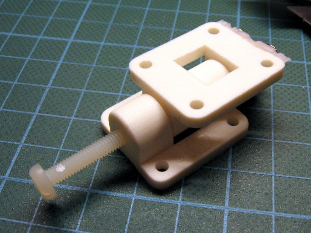
Nylon screw could be secured by a drop of CA on the head side (it shouldn’t move there).
Tail cradle finished (almost – wait for bad suprise further):
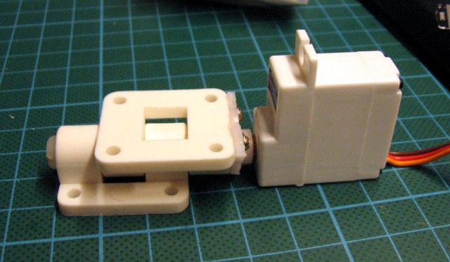
Frame
Center plate of frame should be made from glass fiber. I found im my stuff only plates coated with copper (to make printed circuit boards), so I used them. It will weight a little more, but for my first copter I think that it won’t matter.
I printed template from David’s site and started to cut things:-)
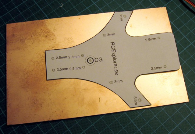
Because I don’t have a CNC machine, I thought at first about ‘coffin’ shape, but with little effort it is possible to cut much better shape only with hack-saw.
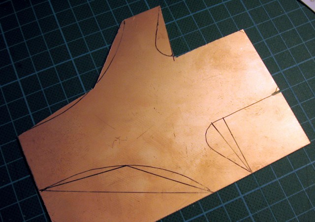
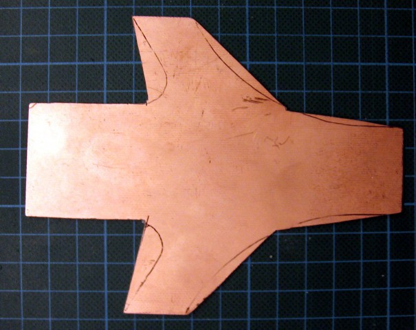
Lucky for me, at this point I switched to making arms. It occured that I bought 12×12 pinewood sticks instead of 10×10…
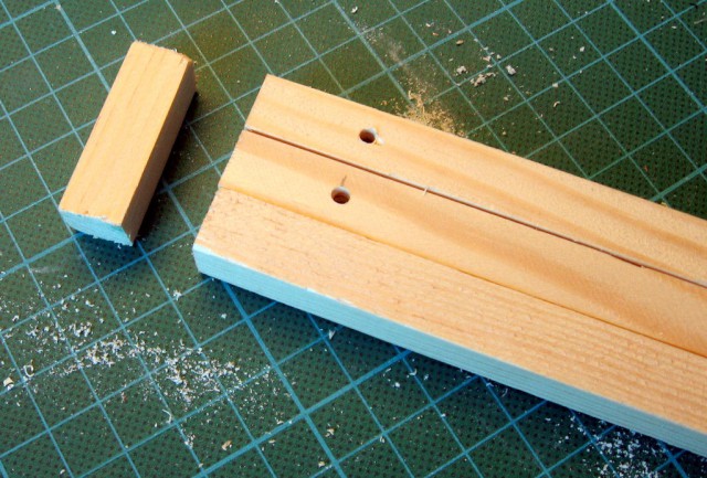
So some holes had to be moved to all parts fit together.
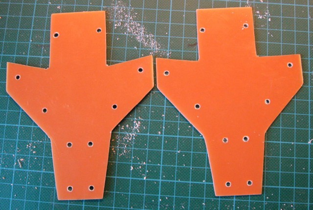
Frame assembly – rember to use thread locker for every nut! I used blue one: HK-171 Thread Locker (blue). I also used only M3 screws as I didn’t have any M2.5.
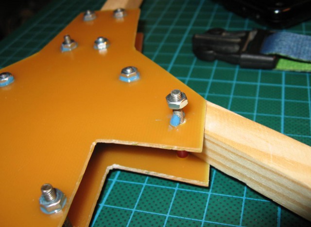
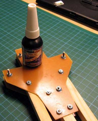
Tail
It’s time to mount some hardware:-)
Few zip-ties and it looks very promising:
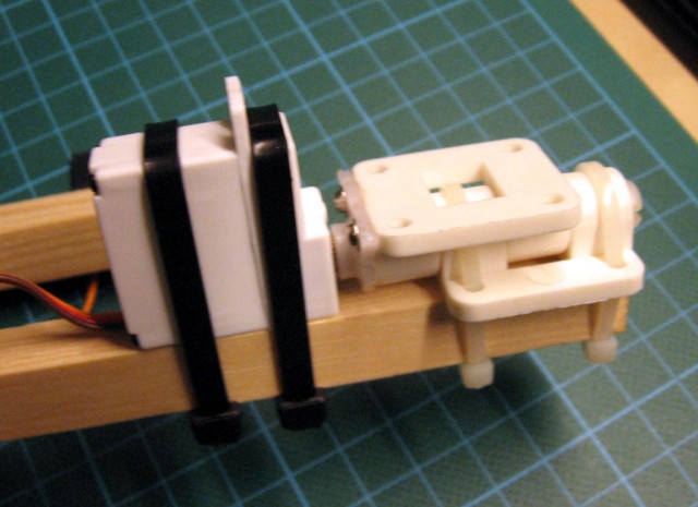
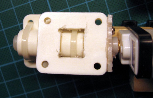
But it only looked that. While I was trying to mount a motor, it occured that there is not enough room for two mounting zip-ties. So I had to use Dremel with 1.5mm drill and make some space for it.
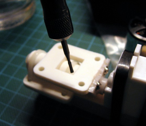
And this was my failure – making holes could be much easier if it was done before mounting everything. But I use another motors, so mounting is also different and I couldn’t predict it. In fact it looked ok during test fitting.
Back to the pictures:
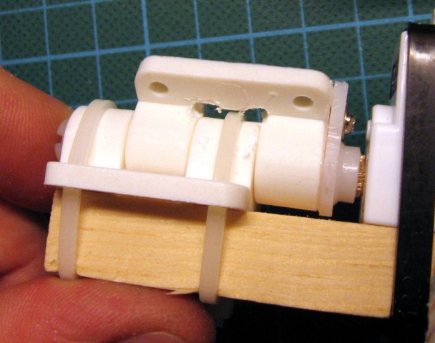
Motors
And finally time was come for motors. I bought 2213N 800Kv brushless motors for this tricopter. I thought about original hexTronik DT750 but that time was unavailable (and it costs few $ more).
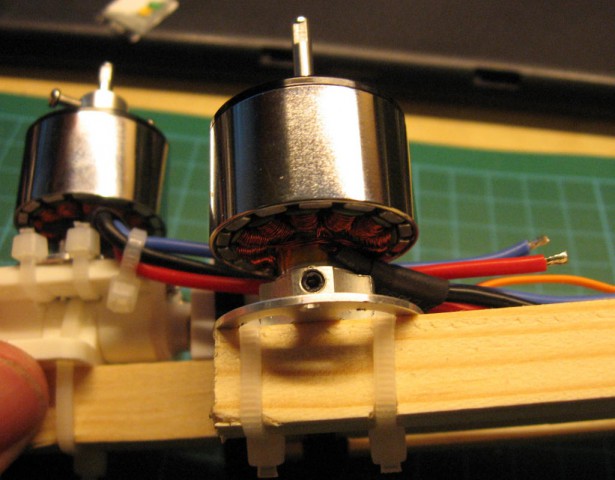
Anyway, to mount this motor to tail 4 zip-ties could be used:
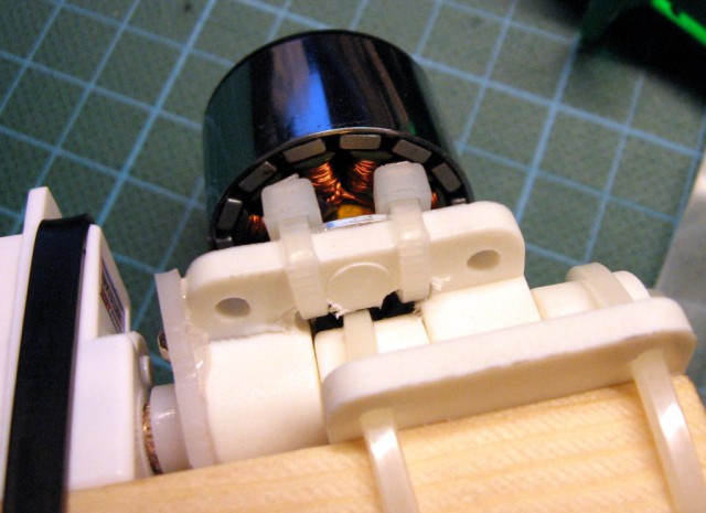
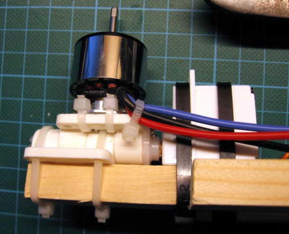
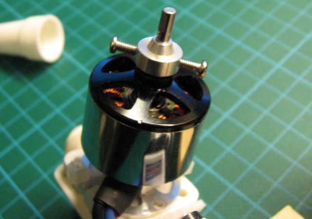
Mounted prop saver on motor shaft. Of course, nuts should be also secured using thread locker.
Zip-ties on other arms:
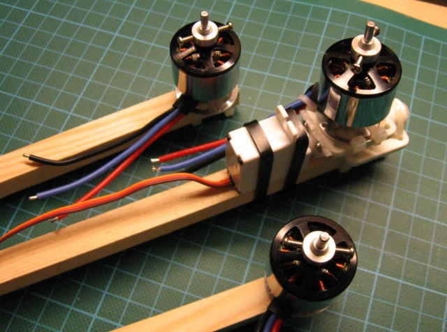
And all motors mounted:
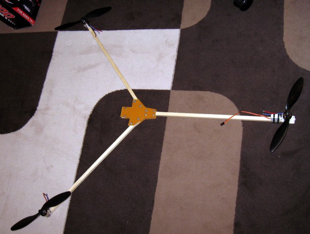
After 2 days of work:
to be continued…
