Cheap and good ESC for Tricopter
ESCs are needed for every multirotor. Some are cheap, but dedicated to planes (slower response), some have extra features in firmware, but costs a little more.
But thanks to SimonK and his firmware, there is possibility to reprogram many of them. So, to build my Tricopter I decided to buy cheapest one available and reprogram it:
HobbyKing SS Series 15-18A ESC
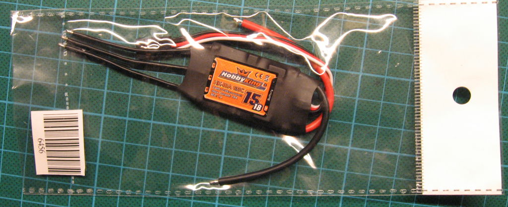
So, let’s modify it 🙂
Hardware
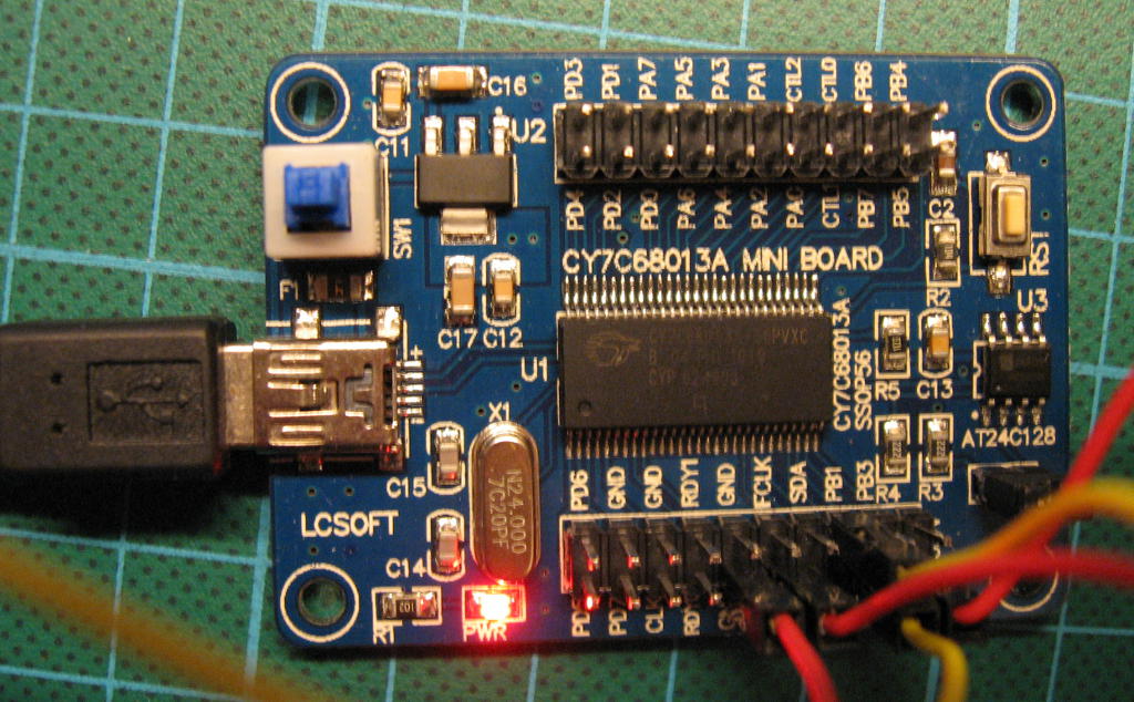
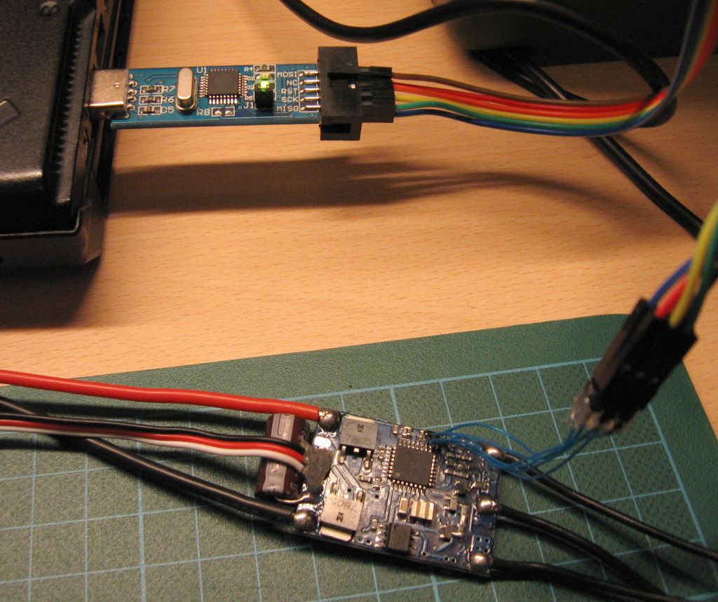
In order to download new firmware you need some Atmel programmer (I use USBasp from HobbyKing but on eBay you should get better and cheaper version supporing both 3.3V and 5V logic levels). Also you need some real soldering skills, steady hand and possibly magnifying glass 🙂
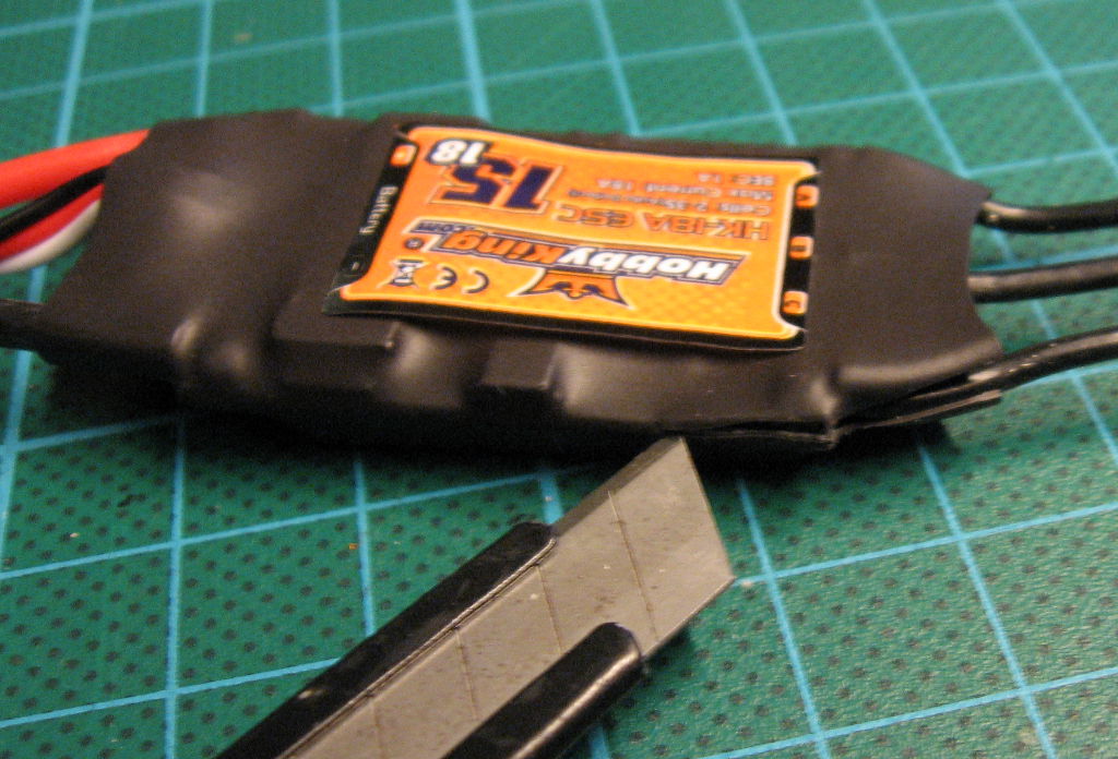
At start: remove shrink-wrap from ESC. The best and safest place to cut it is on one side.
After getting shrink-wrap off, first surprise: I have probably new version of pcb because it looks a little different than on pictures from list of supported ESCs. But luckily it’s almost the same but with added programming pads:
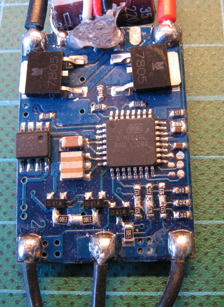
As you can see on above picture there are 6 pads. But bad news is that some are clean and flat, and other one are with ‘balls’ of tin (and on each ESC there were different combination of these). This makes difficult to make some programming connector to touch reliable to these pads.
So, only soldering left for me.
To solder without problems to such small pads I made ‘balls’ of tin on all pads:
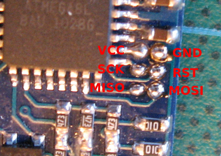
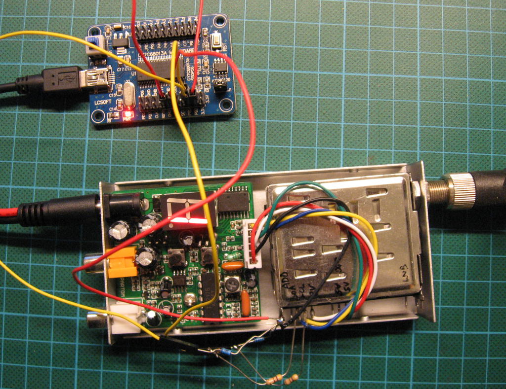
Then I soldered header pin connector with very thin wires (Kynar wires, diameter 0.2mm/AWG32). If you first tin end of this wire, then soldering it to the ‘balls’ on pcb is easy (with magnifying glass 🙂 ).

And just connect it to USBasp and program it!
Software
Of course you need software to flash it into ESC 🙂
Getting it
I got it directly using:
Then I modified tgy.asm to disable runtime calibration:
In my opinion this is not needed for this ESC as it has quartz oscilator and will be controlled by MultiWii board instead of receiver.
Code compilation
avra -fI -o tp_8khz.hex -D tp_8khz_esc -e tp_8khz.eeprom -d tp_8khz.obj tp_8khz.asm
AVRA: advanced AVR macro assembler Version 1.3.0 Build 1 (8 May 2010)
Copyright (C) 1998-2010. Check out README file for more info
AVRA is an open source assembler for Atmel AVR microcontroller family
It can be used as a replacement of 'AVRASM32.EXE' the original assembler
shipped with AVR Studio. We do not guarantee full compatibility for avra.
AVRA comes with NO WARRANTY, to the extent permitted by law.
You may redistribute copies of avra under the terms
of the GNU General Public License.
For more information about these matters, see the files named COPYING.
Pass 1...
Pass 2...
done
Used memory blocks:
Data : Start = 0x0060, End = 0x008C, Length = 0x002D
Code : Start = 0x0000, End = 0x03ED, Length = 0x03EE
Code : Start = 0x0E00, End = 0x0FDF, Length = 0x01E0
Code : Start = 0x0FE0, End = 0x0FFF, Length = 0x0020
Assembly complete with no errors.
Segment usage:
Code : 1518 words (3036 bytes)
Data : 45 bytes
EEPROM : 0 bytes
If you don’t want or you are unable to compile this code, firmware compiled by me is here.
Programming firmware
In this step you need Avrdude or other AVR programming software which allows to flash ready firmware in Intel Hex format.
avrdude -c usbasp -B.5 -p m8 -U flash:w:tp_8khz.hex:i
avrdude: set SCK frequency to 1500000 Hz
avrdude: warning: cannot set sck period. please check for usbasp firmware update.
avrdude: AVR device initialized and ready to accept instructions
Reading | ################################################## | 100% 0.01s
avrdude: Device signature = 0x1e9307
avrdude: NOTE: FLASH memory has been specified, an erase cycle will be performed
To disable this feature, specify the -D option.
avrdude: erasing chip
avrdude: set SCK frequency to 1500000 Hz
avrdude: warning: cannot set sck period. please check for usbasp firmware update.
avrdude: reading input file "tp_8khz.hex"
avrdude: writing flash (8192 bytes):
Writing | ################################################## | 100% 5.02s
avrdude: 8192 bytes of flash written
avrdude: verifying flash memory against tp_8khz.hex:
avrdude: load data flash data from input file tp_8khz.hex:
avrdude: input file tp_8khz.hex contains 8192 bytes
avrdude: reading on-chip flash data:
Reading | ################################################## | 100% 4.38s
avrdude: verifying ...
avrdude: 8192 bytes of flash verified
avrdude: safemode: Fuses OK
avrdude done. Thank you.
Bootloader
Above code contains a bootloader, so further reprogramming could be very easy and could be done using only BEC/PPM connector. But for such programming you will need another device: Turnigy USB Linker or you could do it yourself using Arduino board and ArduinoUSBLinker software.
In order to bootloader works, it’s needed to change BOOTSZ and BOOTRST bits, so new value of hfuse should be 0xca (or 0xc2 if eeprom should survive chip erase).
avrdude: warning: cannot set sck period. please check for usbasp firmware update.
avrdude: AVR device initialized and ready to accept instructions
Reading | ################################################## | 100% 0.01s
avrdude: Device signature = 0x1e9307
avrdude: reading input file "0xca"
avrdude: writing hfuse (1 bytes):
Writing | ################################################## | 100% 0.00s
avrdude: 1 bytes of hfuse written
avrdude: verifying hfuse memory against 0xca:
avrdude: load data hfuse data from input file 0xca:
avrdude: input file 0xca contains 1 bytes
avrdude: reading on-chip hfuse data:
Reading | ################################################## | 100% 0.00s
avrdude: verifying ...
avrdude: 1 bytes of hfuse verified
avrdude done. Thank you.
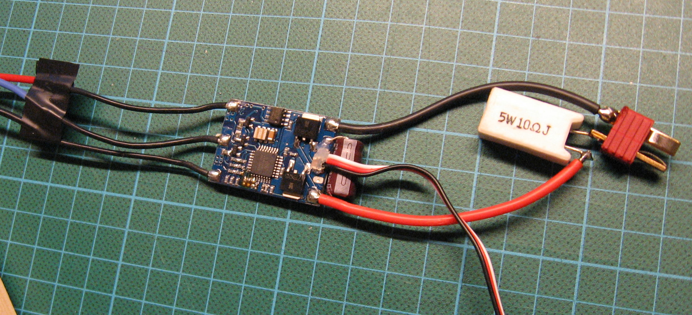
Testing
I recommend to connect ESC to battery first time using 10 Ohm resistor (few Watts recommended). It’s value is small enough to allow motor start and run, but it’s also large enough that any software or hardware malfunction couldn’t burn your ESC.
And on the end – small video with original and flashed ESCs with motors: