G-OSD schematic diagram and making new analog input to it.
I was very curious how everything is connected in G-OSD. It is similar to E-OSD but different – they added potientiometers, analog inputs and gps. And there was also one mystery: third pot that trims RSSI and do nothing in CL-OSD🙂
So, I made it:

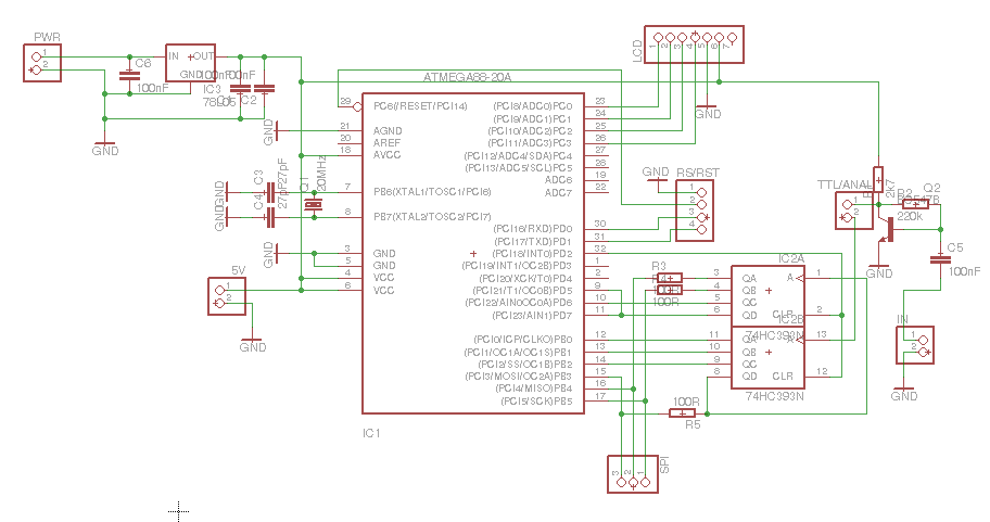
G-OSD schematic diagram
Some conclusions from this schematic arrived:
– third pot really does nothing unless you want to measure 5V from voltage regulator 🙂
– acording to resistor values in voltage dividers, maximum voltage on both inputs could be as high as 23V. I don’t know at how high voltage is rated 10uF capacitor (probably it’s 50V) on battery input, so be carefull with this input. But on Voltage2 it is safe to apply up to 24V.
– video generation circuit is exactly the same as in E-OSD
– pin for RSSI haven’t filtering capacitor, so it could be used also as digital input (for example for measuring RSSI PWM directly from FrSky receiver)
And I used opportunity to make something based on information I learned from schematic and pcb investigation: new analog input! 🙂
So, I made useless pot useful 🙂
Warning: this input has some limitations:
– low input resistance (1kOhm), so it’s not good for current sensor as it require at least 4.7k. Some simple RSSI pwm converters based on passive elements could also work wrong with it.
– voltage from pot goes directly to processor, so putting voltage higher than 5V and turning around this pot without extreme care could end up with death of uC
If you want to measure voltage higher than 5V, put additional resistor in series with this input to be safe. For example for 3C battery, use 2k or 2.2k. If you want more, the rule is: 1kOhm (or more) for every additional 5V.
Now you know limitations of this new input, so let’s do this 🙂
This is my second mod (here is previous), so don’t be surprised by additional pins on pictures, it’s still G-OSD 🙂
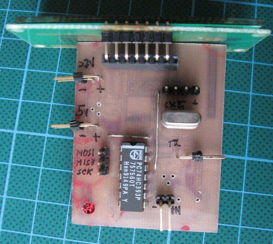
At start (it’s obvious 🙂 ) you should remove shrinkwrap. Then locate third pot (RSSI) and capacitor below it. Please observe that between them there is also a via (small drill/hole). You must cut trace (under white paint) between capacitor and the via as shown on picture:

G-OSD – new input – where to cut trace
And then you have on opposite side of pcb quite large pad to solder new input:

G-OSD – new input pad
Do you want it look well and professional? Stay with me for another few pictures 🙂
Get new angle pinheader, remove unnecessary pins and cut middle two pins to the edge of plastic as on this picture:

G-OSD – new input – preparing new pinheader
Get CA and glue pinheader to pcb with pins in right position:

G-OSD – new input – glue new pinheader into place using CA
After few seconds everything is steady, so you could easily solder pins to pads below:

G-OSD – new input – solder connections
Now you have one pad connected to new input, second one you can connect by wire to some near gnd pad.
Now you can put new heat wrap, and that’s all.
But…
I don’t like make things twice, so I put few addidtional pins as RFU (and there will be nice to connect i2c and tx pins in future 🙂 )
")
G-OSD – more inputs 🙂
")
G-OSD – like a new 🙂


")


")