LCD88: R/C DIY transmitter
Another one? 🙂
There are some other open source transmitter projects, so why did I start another one?
At first, I started it in 2009 – there wasn’t too much free options avaliable, ready made transmitters were also very expensive. And last, there weren’t enough flexible for me :-). Even right now I don’t know if similar transmitter exists, at least at affordable price, not thousands of $$ 🙂
BLOCKS!
The gist of this project is: BLOCKS!
For each model you have some sticks, pots, switches and output channels. Between inputs and outputs there is more or less flexible ‘black box’.
In my project you could define exactly what is in this ‘black box’ by connecting math blocks together in absolutely free way.
Blocks could do:
- trims
- reverse
- add
- substract
- negate
- expo
- multiply
- convert any analog value to 3 state (for switch conditioning)
- some casual mixers
- limits
- and many more…
Better explanation is just to show some examples, so look at them!
For examples you should only know that channels 0-7 are inputs, 16-23 are outputs, some has special meaning or are reseved but right now it’s not important.
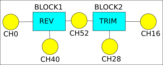
Simple model – as in all entry level transmitters
Channel 0 (CH0) is stick input, value goes into reverse block. Another input for this block is CH40 which remebers reverse position. Output of reverse block goes to channel 52. Another stage is trim block which takes value from channel 52 and adds it to trim value from channel 28. Other channels should be done in similar way.
Special block reverse is in fact a multiply block but it’s treaten in special way – second channel connected to it shows automaticly in ‘Reverse’ menu.
In similar way trim block is an add block which second input shows in ‘Trims’ menu.
Looks easy, isn’t it? So, let’s go ahead.
Delta or flying wing
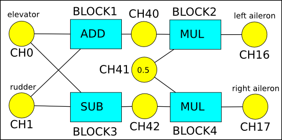
Another example: delta mixer.
At the beggining let’s write some equations:
right aileron = ( - rudder stick + elevator stick ) /2
So let’s draw blocks to calulate it:

Ok, but this is only mixer, what about trims, reverses etc?
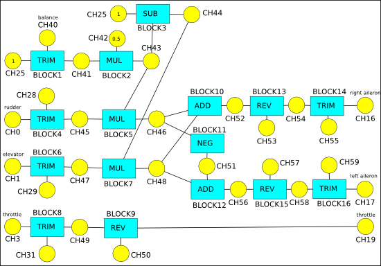
So, look at real life model:

Looks complicated, but let me explain what’s going on.
A little transformed formula for delta mixer in this case:
left aileron=0.5*elevator-0.5*rudder
I think that most people who flies flying wing could confirm that this type of model is very sensitive to elevator moves. One solution for this is to make expo/DR on elevator channel. But I preffer make elevator just less sensitive in favor to rudder. So, instead of using 0.5 coefficient to multiply values from both channels, I use smaller one for elevator and greater for rudder. If coeficcients sum up to 1, results will be still within allowed range (I already did it on my standalone delta mixer based on ATTINY13).
Let’s look at above picture. Blocks 1-3 are here to make flexible coefficients. On Block1 input is 1 (CH25) and trim (CH40), so it makes at output (CH41) value in range 0…2 dependent on trim position. It’s too big to further calculations, so we must scale it down using Block2. At it’s output (CH43) we have value in range 0…1. Block3 calculate second coefficient for multiplication (CH44=1-CH43). Blocks 5,7,10,11,12, form a delta mixer with adjustable amplification for both control sticks. After delta mixer, there are reverse and trims blocks to adjust servo direction and neutral point. Near input there are blocks 4,6 and 8 – there are standard trims for fine tuning during fly.
So, as long as you could make some equations to describe how channel values should be processed, you could make it.
Enough about blocks:-) Let’t go to other topics.
Software architecture
There are few types of tasks inside transmitter:
- critical – generating accurate PPM
- high priority – get values from inputs, calculate blocks and store results for PPM
- best effort – user interface (menu, displaying something on LCD, trims, options etc.)
Generating PPM
I use hardware PWM generator to make an accurate PPM signal. In best possible way 🙂
That’s possible because of using timer in CTC mode and interrupts with right, but not so critical place in time. The point is that writing new value to timer in this mode during generating waveform is effective only for new cycle and doesn’t affect current operation, so it could be calculated and programmed anytime during this period. I calculate it just after end of synchro pulse (in interrupt triggered by this event), so CPU has at least 10000 clocks to do it, and this is more than enough. Because of that, there is absolutely no jitter and pulses are just perfect. 🙂
Getting values, calculating it and other things
That’s another cool solution here: multitasking in AVR!
After copying output values to buffer for generating PPM, CPU starts getting analog values from ADCs (using interrupts). They are filtered and recalculated and results are put in input channels. Meantime 2 thing are running: PPM generation using interrups and user interface or other not critical things. When all values from inputs are ready, a task switch occurs. User interface thread is interrupted, state is saved to ram and block calculation task begins. After processing and calculating all blocks, this task ends and switches back to user interface task.
This way PPM is generated perfectly, calculating blocks is done in high priority thread, and the rest fo time could be used to draw some fancy things on color LCD 🙂
Great advantage of multitasking is that during programming user interface I could do whatever I want without bothering myself about timing as long as interrupts are enabled.
Memory
I decided to use internal flash memory as main storage for model definitions (blocks, initial channel values etc.). I organized data into containers with headers containing information about model number, contents of container (block, channel, comment…) and length. And one important rule: there could be many containers with the same ‘id’ but only last in memory is valid. It makes updates as simple as writing new version of container at the end of other containers. It also help to reduce flash write/erase cycles. Only drawback is that memody should be compacted from time to time.
But using trims could fill all flash memory very fast, so I decided to make temporary storage only for channels (4 bytes/ch) in eeprom. In future there will be possibility to move values from eeprom back to flash. It will be needed to backup/restore model definitions.
Features
- Model memory (maximum 31).
- Each model comprise of:
- comments, model name is one of them and is mandatory (maximum 256 per model) – they could be assigned to channels and blocks
- channels, some are dedicated to inputs, some to outputs, the rest could be used for trims, reverses, connections between blocks etc. (maximum 253 per model)
- blocks, they do math operations on input channels and store result to another channel(s) (maximum 255 per model)
- block processing order, right now you must manually generate list of blocks in order they should be processed
- 8 output channels, but it could be increased keeping in mind that output frame should be extended
- 8 analog inputs, they can be also ‘conditioned’ and used for switches
- PPM output (super accurate, jitter free, ~11000 steps per channel)
- internal calculations does on 16 bit fixed point numbers (6+10), it is equivalent of more than 2048 steps
- serial bootloader, so firmware upgrade could be done using standard usb-serial cable/interface
- Colour LCD screen
- 6 keys for menu navigation
- Open source! (code will be available soon)
A little bit of history
In 2006, when I started to think about R/C models, I bought cheapest 4 channel transmitter with idea, that if I’ll need more – I’ll make it:-)
Somewhere between 2007 and 2008, during discussion on Alexrc forum, idea of very flexible and fully programmable transmitter were born.
Idea was to define model inside transmitter using basic blocks (sum, multiply etc) and connections between inputs, blocks and outputs.
In 2008 I made a universal board for my projects using Atmega8L and LCD screen from Siemens S65 phone.
In 2009 I replaced Atmega8L with Atmega88 – it allowed to safely (within cpu specs) increase cpu clock up to 11MHz while still running at 3V. And then real story begins:-)
At the end of 2009 I had some things finished: generating ppm, calculating blocks and basics of user interface (menu, keyboard). And then project stuck for almost 3 years.
I tried to make it too universal, and it didn’t worked for UI. During these years I used simple transmitters – there were enough for my planes. But at the end Tricopter appeared:-) Problems with arming control board and need for more channels resurrected old project.
So, at the end od 2012 i removed some code (mostly UI related), revised some assumption (store model definitions not only in flash, but also use eeprom for this), and project moved forward.
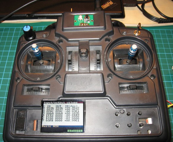
I put this board into empty old transmitter bought at about $2, added FrSky DHT module, connected all together and right now it could be used in real world:-)
Future
- Switch to Atmega168 or Atmega328 (I have both and code is ready – it’s only a matter of doing PCB and solder it together)
- Because right now there is almost impossible to buy S65 LCD display (but I have few 🙂 ), I bought another similar one. Plan is to make code supporting also this new display.
- Change code to run on standard Arduino board based on Atmega328 (check all timings in code and rewrite it to support other cpu frequencies)
- More code, more features (but not on Atmega88 because I already hit memory limit)
- Timers, i/o extender (more inputs, trainer mode)
- …


Hello, nice transmitter 🙂 I especially like the awesome mixer-setup-interface.
I am making something similar using Mega168/328 with GCC ( not Arduino ). I have managed to get PPM input and output using CTC and 1 compare match from Timer1 only, it is completely interrupt driven and runs fine even at 20 MHz. I am about to start implementing my “black box” of mixers. Mostly this project was started due to the inability to use both Delta and Differential mixers on my Graupner MC12. The first version will be a small PCB that connects the output PPM ( student out ) to the input PPM ( student in ) on the same transmitter. This will give me the nice option to bypass my pcb with the student-switch and I can use my normal TX for testing, no need to build a complete transmitter ( yet ). When all the PPM-stuff is OK I might add sticks, knobs switches and some display but I`ll probably move to Cortex M3, I have some NXP-boards floating around.
Any chance of finding your sourcecode somewhere?
My code is managed in git, it´s not so pretty but I´ll be happy to share, perhaps you´ll find the timer1 ppm implementation interesting or useful.
Regards,
Kalars
1. I have my code in svn, but repository isn’t publicly available (yet). My code (warning: pure assembler 🙂 ): https://majek.sh/modele/lcd88-rev117.tgz
2. If I were starting this project today, I would choose definitely some ARM platform (probably STM32) and C as programming language 🙂
3. Keep in mind that interrupt can’t be executed always in exact time (some instructions last longer, some are shorter, some block cpu (eeprom access), sometimes you have to wait for another interrupt to complete). If you use PWM output and program counters before generation, it’s fine. But if you use counter to make interrupt and you toggle pwm output there, you get some delay (not constant) between cause of interrupt and result.
4. Idea of baypass is quite good:-) In my case I could replace all electronics because I have two other transmitters 🙂
5. Regarding 20MHz – it’s a lot of time to do many things:-) I encountered not enough ‘power’ in only 2 cases: drawing on lcd screen (spi could run faster 😉 ) and video overlay generation (in OSD).
Anyway, it’s fun to make such things, but it also require patience and lot of effort to finish it – transmitter is quite complicated thing. In my case making ppm, tasks, ‘black box’ was fun, but whole user interface is just a ‘need to finish/work’.
Good luck wih your project!
Panie Marku czy Pana projekt był kiedyś przepisany na platformę Arduino?
To zależy:-)
Hardware, to dokładnie najmniejsze, najprostsze i najtańsze Arduino.
Co do software, to myślałem nad tym, ale:
– ‘koszt’ przepisania tego byłby za duży
– musiałbym zrobić multitasking dla Arduino (niebanalna rzecz)
– baaardzo zmalałaby pamięć na modele, bo sam kod byłby większy, a obawiam się, że nawet mógłby się nie zmieścić w Atmega328. Wtedy całe założenie, że ma być tanio i dobrze nie będzie już spełnione.
Natomiast niedługo pojawi się inny bootloader (modyfikacja Optiboota), więc łatwiej będzie wgrywać nowy soft (używając avrdude zamiast tajemniczych komend z minicoma). Docelowo ma być również dostępny eksport/import modeli jak i ich modyfikacja w aparaturze, więc wtedy nie będzie potrzebna kompilacja przy każdej zmianie – wystarczy raz wgrać hex-a.
Witam
Na jakim etapie jest obecnie praca nad nadajnikiem? Od dłuższego czasu nie widzę nowych wpisów – czyżby projekt umarł?.. Zapowiadał się całkiem ciekawie, ale chyba nie ma szans na samodzielne wykonanie?..
Fakt, że utknęło to, ale jeszcze się nie poddaję 🙂
Co do używania, to obecnie da się tego używać o ile przemyśli się budowę mikserów w modelu.
Ich zmiana, to niestety nadal przeprogramowanie softu. Chociaż powinno był łatwiej, bo nie potrzeba dedykowanego bootloader-a, a może być zwykły Optiboot. Mając któreś Arduino na Atmega328, to nawet nie trzeba mieć programatora. Avrdude po serialu bez problemu wgra skompilowane oprogramowanie. Natomiast do Arduino trzeba konwerter poziomów, żeby podłączyć wyświetlacz, ale to też można już tanio kupić gotowe.
Natomiast w ‘polu’ można zmieniać trymy, rewersy i same modele, więc nie ma problemu z normalnym użytkowaniem.
Obecna wersja softu dostępna jest na https://github.com/majekw/lcd88