Christmas tree lamps with Arduino and WS2811 leds :-)
Somewhere at the beginning of November I discovered RGB LEDs with embedded controller: WS2812 and others. Idea was so cool for me that I had to own one to play with it 🙂
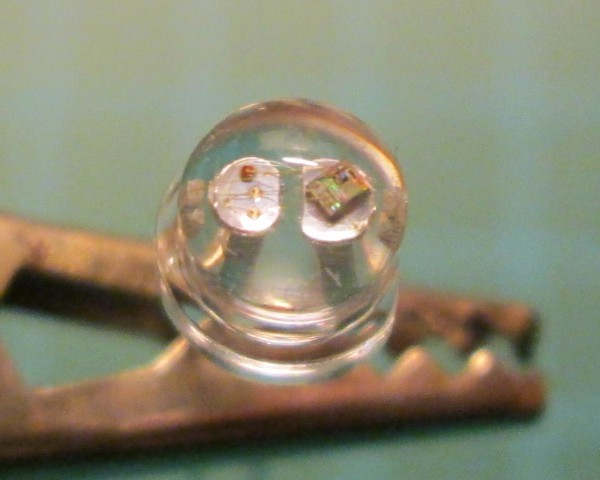
These chips became so common, that there are even put inside LEDs, like on this WS2812 diode:
Considering time of the year, it was obvious to me to make whole string of lamps for Christmas tree. Then I found on Aliexpress ready made chains of such LEDs. 🙂
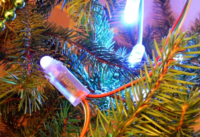
So, my LEDs aren’t with chips inside, but with small PCBs sealed with some kind of hard silicone – maybe not so elegant as chip integrated inside LED, but cheaper – which counts if you buy 50 of them :-):
Day before Christmas I still haven’t done anything with these light, so it was last chance to do something useful with it.
Connecting everything was quite easy as there are only 3 components: 5V power supply, Arduino Pro Mini board and LED chain.
Programming protocol for WS2811 was more challenging – generated waveform must be very accurate, with some time intervals taking only 8 cpu Atmega328 clocks (at 16MHz). So, I chose assembler to do it (as usual 🙂 ).
To be more hardcore, it was 3am when I started debugging 🙂 Honestly, without my new oscilloscope, finding these 3 mistakes I’ve made, could’ve took hours. Especially that Chinese guy who sells these LEDs described them as ‘we sent WS2811. Or we may sent UCS1903’ – two different possible chips (!) with two different protocols and no one knows which version I’ve got.
Luckily for me. it was WS2811, so first guess and code worked.
I added few simple routines to move light across whole chain of LEDs and put everything on Christmas tree.
All code for this ‘one night project’ you could find on my Github page: https://github.com/majekw/wsled
This is how it looks like on my Christmas tree:


The first picture doesn’t actually show a WS2811 LED, rather it’s an autofading RGB LED. The WS2811 would have 2 more leads- Din and Dout signals necessary for control.
Lens distorts view, but definitely all 4 legs are present 🙂
What seems to be some kind of dirt on the left and on the right, there are ‘missing’ legs. On the left you can also spot bonding wire. Two center legs have also much larger ends to make support for chip (on the right) and leds (on the left).
I could make picture with side view if you still not believe 🙂
However, thank you for comment 🙂
I pity the guy deep in china who had to solder all these les elements to the tiny pcb before they were encased 😉
lovely setup though