Logic analyzer
This time there will be a combined article – something about my new toy: logic analyzer, but also there will be introduction to diversity video receiver.
Logic analyzer
If you do anything with digital equipment or diy projects etc, logic analyzer could be very helpful tool for debugging. It’s great also for reverse engineering 🙂
From some time I had in my mind The Fabulous Logic Analyzer but parallel port is not what is available in modern laptops 🙁
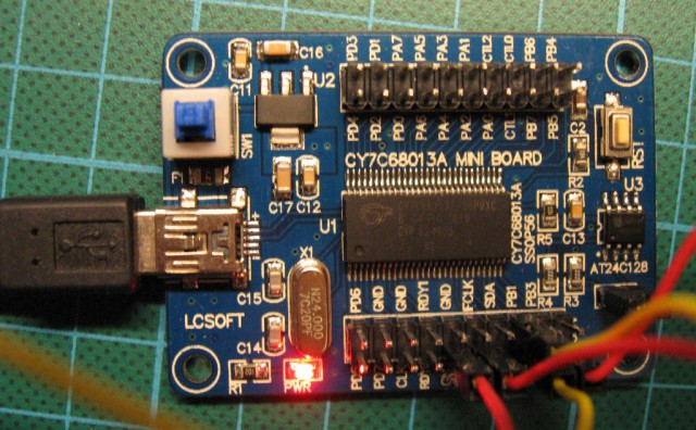
Then I saw how Saleae Logic16 works:-) It was impressive, especialy that it works also under Linux. But 100-200 euros are a little over my budget for new toy, so I started searching for affordable alternatives. After some digging on the Internet, I found that old Saleae Logic, CWAV USBee SX and other cheaper logic analyzers are based on Cypress CY7C68013A chip and have almost nothing more than this chip alone. So, I found on Ebay Lcsoft CY7C68013A Mini Board prototyping board at less than $12 and now I have one 🙂

It’s not compatible with Saleae despite of programmed USB VID/PID. But because I try to use opensource where possible, so my only choice was Sigrok.
After getting hard time to meet Sigrok dependency (Python3, sdcc and other unusual software), it compiled and started to run. Sigrok comes with it’s own firmware for Cypress chip, so no pirating here:-)
It’s even better, because Lcsoft board has jumper to switch between ‘Saleae mode’ and ‘Cypress Development Kit’.
In Saleae compatible mode, Sigrok uploads standard firmware, so only 8 inputs are available at 24MHz sample rate.
But when we switch to ‘native’ mode, we have logic analyzer with 16 inputs 🙂 Of course 16 bit sampling is not available at 24MHz but when we narrow count of inputs up to 8, full sample rate is still available.
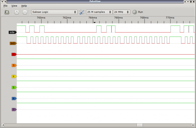
Sigrok is quite new project, so gui is not it’s strong side, but at least there is possibility to sample and look at waveforms, and that’s all – even saving of sampled data is not available in gui 🙁

On the contrary, command line sigrok_cli is quite powerful.
Analyzing video receiver
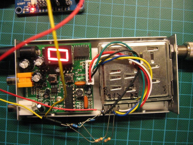
So, it’s time to analyze something, and standard video receiver which comes with Fox700 transmitter as bundle is ideal for it 🙂
I was wondering from some time what exactly happens on i2c bus, ie. how tuner is programmed for specific frequency, and an opportunity to get it known arrived 🙂
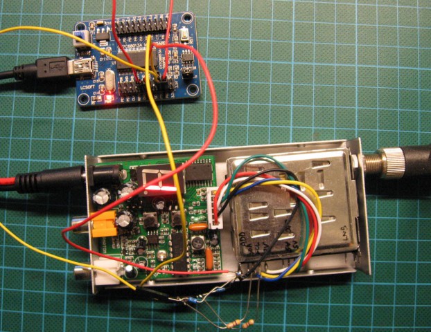
As you can see on the above pictures, I added simple level converters with resistors and Zener diodes. It’s because logic of video receiver is 5V and Cypress is 3.3V chip. Of course I tried without Zener diodes, but weird things were happening 🙂
Sampling with sigrok_cli:
libsigrok 0.2.0
Acquisition with 8/16 probes at 24 MHz
0:00000000 00000000 00000000 00000000
1:00000000 00000000 00000000 00000000
2:00000000 00000000 00000000 00000000
3:11111111 11111111 11111111 11111111
4:11111111 11111111 11111111 11111111
5:11111111 11111111 11111111 11111111
6:11111111 11111111 11111111 11111111
7:11111111 11111111 11111111 11111111
Ones and zeros are fine, but real power of Sigrok is ability to decode protocols:
$ sigrok-cli -i test.sr -a i2c:sda=0:scl=1
i2c: "START"
i2c: "ADDRESS WRITE" "0x68"
i2c: "ACK"
i2c: "DATA WRITE" "0x05"
i2c: "NACK"
i2c: "STOP"
i2c: "START"
i2c: "ADDRESS READ" "0x50"
i2c: "ACK"
i2c: "DATA READ" "0x00"
i2c: "NACK"
i2c: "STOP"
i2c: "START"
i2c: "ADDRESS WRITE" "0x61"
i2c: "ACK"
i2c: "DATA WRITE" "0x2b"
i2c: "ACK"
i2c: "DATA WRITE" "0x6c"
i2c: "ACK"
i2c: "DATA WRITE" "0x8e"
i2c: "ACK"
i2c: "DATA WRITE" "0xf0"
i2c: "ACK"
i2c: "STOP"
Initial write and read are some junk, I think that chip used for programming tuner, had originally other purpose and peripherials, but what is really interesting is data written at address 0x61.
According to documentation of SP5055 (synthesizer used on most tuners), 0x61 is it’s ‘always valid’ address, despite of signal on address settings pin, so it always works.
During that write there are 4 bytes transferred: 2 bytes of divider (unique for each selected channel), and 2 bytes for setting state of chip and external outputs (always the same).
So, let’s check what tuned frequency should be.
Divisor is 0x2b6c (MSB is transferred first) = 11116
According to datasheet, tuned frequency is:
f = divisor * 16 * Fcomp
Fcomp is frequency of quarz or external generator (typically 4MHz) divided by 512, so:
f = divisor * 16 * 4000000 / 512
In this case synthesizer is tuned to 1389500000Hz = 1389.5MHz
But that’s not the end – we must substract intermediate frequency 479.5MHz of tuner.
So, in fact we are tuned to 910MHz and this is exactly a 0 channel which was set on this receiver during test.
Success! 🙂
One thing I’m missing in sigrok_cli is lack of timestamps (number of samples could be shown using -v flag), but it’s open source and everyone could add this (maybe even I) 😉
Right now, when I know how to control tuner in receiver, I could make my own controller.
Why? Because documentation of SP5055 and some tuners shows that there is possibility to read also some data from tuner. Most interesting is little ADC connected typically to circuit that shows offset between set and receiving frequency. With this information it’s possible to automatically fine tune to exact frequency. It’s also possible to follow frequency change while transmitter warms up. And of course it’s possible to tune to any frequency in tuner range with 125kHz step 😉
Tuning multiple tuners at once isn’t also a problem, so making simple diversity based on video rssi it’s also possible,


Hi! Would you mind to give me an email where I could write? Thanks
many thanks, this info was exactly what I was looking for!
question: where did you get the 479.5MHz value, and how did you know that you needed to subtract it from the calculated frequency value? I searched the SP5055 datasheet for this information yet couldn’t find it.
These receivers use old analog satellite tuners in which 479.5MHz is common intermediate frequency. For example you could check datasheet of this one: http://www.dpcav.com/xcart/Comtech-BSS479LAIDF-Analog-Tuner-Module.html
So, having intermediate frequency you have only two choices: pll should make lower or higher frequency with offset of 479.5MHz to received frequency. Typically higher one is choosen. In these tuners is reasonable as it’s lower receiving frequency is about 900MHz (960-480=trouble).
hi and thanks
i want to used tuner with avr. but I do not know how and what kind of tuner should I use? (i2c)
I think the tuner ” sharp BSFJ78G29 ” is good because pll- i2c type, but I do not know how to set : the frequency, symbol rate, vertical or horizontal,…?
can you help me? something like notes about BSFJ78G29 i2c protocol and …..
thanks alot
It looks like this tuner have SP5655 tuner which is almost the same as SP5055. If you google for ‘sharp BSFJ78G29’, you can find tuner datasheet. It clearly states that pll chip is SP5655 which is the one you should talk to via i2c. Datasheet for SP5655 is also easily found by google.
Do you found some stock of this tuners? Narrow bandwidth is quite good feature. Maybe I could buy one or more if price is good 🙂
About symbol rate and polarization – what do you want to do with it? It’s analog tuner and I think that almost nothing is available these days on satellite in that way. Symbol rate is domain of digital transmission. Polarisation is also another story as it is modulation of power supply for receiving head, and this is also not related with tuner iself.
thanks majek
i want to analysis some sat frequency features for example signal strength,…. but i do not know How to do it? i searched but i founded some thing like sharp tuner. In your opinion, what tuner I choose?(digital and i2c if possible)
Digital tuners differ a lot from analog ones. In analog almost everything important is inside tuner module, everything outside is just audio separation, equalization and control. Digital tuner is another story – much harder for hobbyist. I’m not familiar with all that demodulation, i/q things and so on (which is processed outside of tuner module), so in this part I couldn’t help you.
So, for analog sattelite – it quite easy to use tuner module to do something (it has rssi analog output, information about frequency lock/deviation is availavle from i2c registers).
For digital measurement I would definitely get PC satellite card – there is a lot of tools which shows signal strength, ber, transport streams, etc in real time. From my experience tuning to get maximum gain sometimes doesn’t work – it’s better to do fine tuning based on ber – and to do it you need complete receiver.
thanks alot majek with you help i can set frequency but
How to check signal information for example signal strength with sharp BSFJ78G29 tuner? (true signal or not)
Signal strength should be available on AGC OUT pin – it’s analog value.
Additionally you could check internal ADC on P6 and FL flag to check if frequency is locked right (assuming that this tuner have such internal connection).
For some clues you could check datasheet of other tuner: http://www.dpcav.com/data_sheets/Comtech_BSS-479.pdf
U mnie w tunerze (receiver dla modelarskich nadajników video 1.2G), właściwie głowicy, siedzi nie sp5055 a TA550A (toshiby) z kwarcem 4MHz i TA8804 z kwarcem 479,58 (okrągłe ustrojstwo, może to nawet generator jest).
Miałem kłopot ze znalezieniem datasheetu od tego TA550A – może kolega pomoże.
Dzięki z góry za pomoc.
Nie znalazłem nic do TA550A, ale podejrzewam, że jest kompatybilny z SP5055. Też typowo wymaga kwarcu 4MHz i raczej dziwne byłoby jakby gadał jakimś innym protokołem. Najlepiej wziąć jakiś analizator stanów logicznych i się przekonać 🙂
Co do ‘kwarcu’ 479.58, to jest to filtr pośredniej częstotliwości. Od niego zależy selektywność odbiornika i dlatego często jest wymieniany na węższy (do satelity stosuje się szerokie, ale do bezpośredniego odbioru na 1.2G typowy jest za szeroki i łapie też dużo śmieci i sąsiednie kanały).
Hi there,
Great info! 🙂
Did your board come with firmware to use as an analyser, or did your download/write your own?
Hi All, thank you for this info.
Finally I tried also to pilot this RX 23 cm, and it works fine on the I2C address “2C”. with a single PIC 16F84A and a F6ICX program for COMTECH receiver…
Now I ‘m rewriting the same prog for arduino nano and I2C LCD…