BLOCKS!
The gist of this project is: BLOCKS!
For each model you have some sticks, pots, switches and output channels. Between inputs and outputs there is more or less flexible ‘black box’.
In my project you could define exactly what is in this ‘black box’ by connecting math blocks together in absolutely free way.
Blocks could do:
- trims
- reverse
- add
- substract
- negate
- expo
- multiply
- convert any analog value to 3 state (for switch conditioning)
- some casual mixers
- limits
- and many more…
Better explanation is just to show some examples, so look at them!
For examples you should only know that channels 0-7 are inputs, 16-23 are outputs, some has special meaning or are reseved but right now it’s not important.
Simple model – as in all entry level transmitters
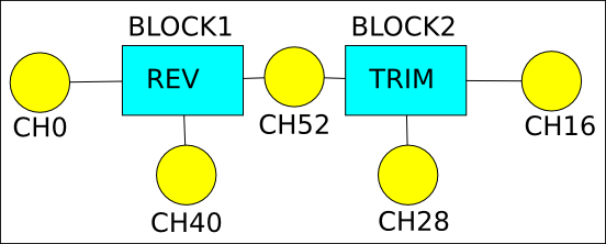
Channel 0 (CH0) is stick input, value goes into reverse block. Another input for this block is CH40 which remebers reverse position. Output of reverse block goes to channel 52. Another stage is trim block which takes value from channel 52 and adds it to trim value from channel 28. Other channels should be done in similar way.
Special block reverse is in fact a multiply block but it’s treaten in special way – second channel connected to it shows automaticly in ‘Reverse’ menu.
In similar way trim block is an add block which second input shows in ‘Trims’ menu.
Looks easy, isn’t it? So, let’s go ahead.
Delta or flying wing
Another example: delta mixer.
At the beggining let’s write some equations:
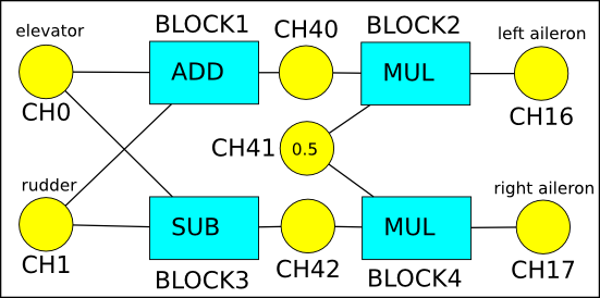
right aileron = ( - rudder stick + elevator stick ) /2
So let’s draw blocks to calulate it:

Ok, but this is only mixer, what about trims, reverses etc?
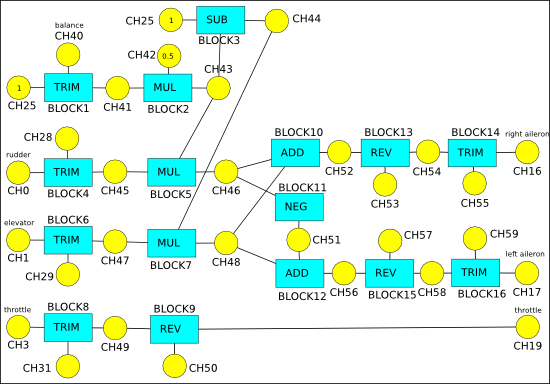
So, look at real life model:

Looks complicated, but let me explain what’s going on.
A little transformed formula for delta mixer in this case:
left aileron=0.5*elevator-0.5*rudder
I think that most people who flies flying wing could confirm that this type of model is very sensitive to elevator moves. One solution for this is to make expo/DR on elevator channel. But I preffer make elevator just less sensitive in favor to rudder. So, instead of using 0.5 coefficient to multiply values from both channels, I use smaller one for elevator and greater for rudder. If coeficcients sum up to 1, results will be still within allowed range (I already did it on my standalone delta mixer based on ATTINY13).
Let’s look at above picture. Blocks 1-3 are here to make flexible coefficients. On Block1 input is 1 (CH25) and trim (CH40), so it makes at output (CH41) value in range 0…2 dependent on trim position. It’s too big to further calculations, so we must scale it down using Block2. At it’s output (CH43) we have value in range 0…1. Block3 calculate second coefficient for multiplication (CH44=1-CH43). Blocks 5,7,10,11,12, form a delta mixer with adjustable amplification for both control sticks. After delta mixer, there are reverse and trims blocks to adjust servo direction and neutral point. Near input there are blocks 4,6 and 8 – there are standard trims for fine tuning during fly.
So, as long as you could make some equations to describe how channel values should be processed, you could make it.


Comments
LCD88 – how it works — No Comments
HTML tags allowed in your comment: <a href="" title=""> <abbr title=""> <acronym title=""> <b> <blockquote cite=""> <cite> <code> <del datetime=""> <em> <i> <q cite=""> <s> <strike> <strong>