Modyfikacja G-OSD – nowe wejście
Schemat G-OSD i wykonanie kolejnego wejścia analogowego.
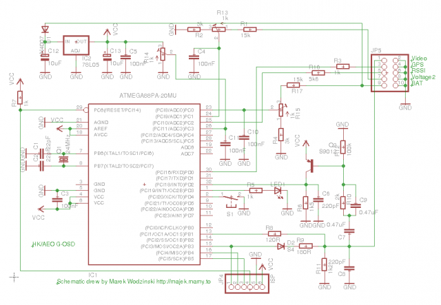
Byłem ciekawy jak wygląda w środku G-OSD, które zakupiłem jakiś czas temu. Na rcgroups jakoś nikt się nie kwapił do rozrysowania schematu mimo powstania alternatywnego softu. W stosunku do E-OSD dodano potencjometry do ręcznego trymowania napięć, jedno wejście niskonapięciowe dla RSSI i wejście na gps. No i pojawiła się też zagadka dlaczego w alternatywnym sofcie (CL-OSD) jeden z potencjometrów nic nie robi.
No to w końcu przysiadłem i narysowałem:
Na podstawie schematu można wyciągnąć już pewne wnioski:
– trzeci potencjoments podłączony jest pod 5V i niczego użytecznego sam z siebie nie robi. W oryginalnym sofcie robi za napięcie odniesienia dla RSSI i proporcje między tym wejściem a wejściem sygnały przelicza procesor.
– wnioskując po wartościach rezystorów z dzielników napięć na wejściach 'wysokonapięciowych’, można tam podać bez szkody dla układu nawet do 24V. Ewentualny problem na wejściu zasilającym może stanowić kondensator (ale najprawdopodobniej jest on na 50V) oraz czy stabilizator 78L05 wytrzyma termicznie (chociaż testowałem układ na ok. 18V i nie było tragedii).
– układ generowania obrazu jest identyczny jak w E-OSD
– wejście RSSI jest pozbawione kondensatora filtrującego jak i dzielnika napięcia (tylko rezystor w szereg), więc może służyć również jako wejście cyfrowe (np. do podłączenia bezpośredniego RSSI po PWM np. z odbiornika FrSky)
Mając już zdjętą koszulkę i parę przemyśleń ze schematu nie mogłem oprzeć się kolejnej modyfikacji 🙂
Tym razem kolejne wejście analogowe i przy okazji trzeci potencjometr na coś się przyda.
Uwaga: to wejście ma pewne ograniczenia:
– niska rezystancja wejściowa (1kOhm), więc nie będzie dobre do czujnika prądu jako, że wymaga on co najmniej 4.7k. Niektóre wyjścia RSSI również (zwłaszcza proste przejściówki pwm->analog) mogą przekłamywać w takim układzie.
– napięcie ze ślizgacza potencjometru wchodzi bezpośrednio na procesor, więc podłączanie pod to wejście bezpośrednio napięcia wyższego niż 5V i nieuważnym kręceniu potencjometrem może się źle skończyć dla procesora.
Najlepszym wykorzystaniem dla tego wejścia jest mierzenie napięcia baterii wstawiając w szereg dodatkowy opornik, który poszerzy zakres pomiaru, a jednocześnie zabezpieczy procesor przed przypadkowym złym pokręceniem potencjometrem, Dodatkowo dla baterii rezystancja rzędu kilku kOhm nie jest problemem. Dla przykładu do pomiaru pakietu 3C najlepiej użyć rezystora w szereg o wartości 2k lub 2.2k. Dla innych baterii za regułę można przyjąć 1kOhm (lub więcej) na każde dodatkowe 5V zakresu pomiarowego.
Teraz kiedy znasz już ograniczenia nowego wejścia, można przystąpić do dzieła:-)
To jest już moja druga przeróbka G-OSD (tutaj jest poprzednia), więc nie bądź zaskoczony innym wyglądem modułu na zdjęciach, to nadal jest G-OSD:-)
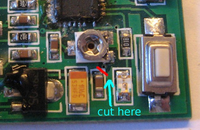
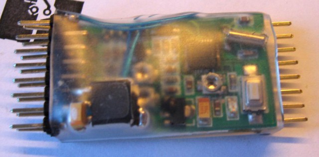
Na początku (oczywiście) trzeba zdjąć koszulkę termokurczliwą. Następnie znaleźć potencjometr od RSSI i kondensator poniżej. Jak się przyjrzeć, to pomiędzy nimi jest jeszcze mała przelotka. Trzeba przerwać ścieżkę (pod białą farbą) pomiędzy przelotką a kondensatorem tak jak na obrazku:
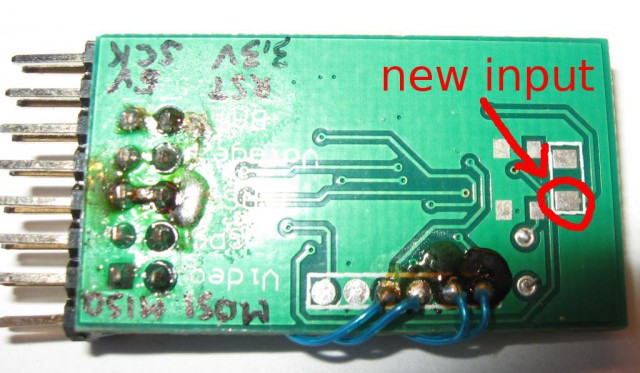
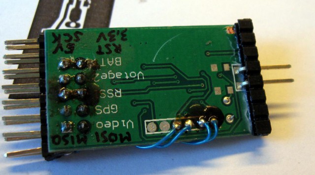
Po drugiej stronie płytki jest całkiem spory pad do przylutowania nowego wejścia:
Chcesz, żeby wszystko wyglądało jak z fabryki? Nie kończ jeszcze, ale pooglądaj kolejne zdjęcia 🙂
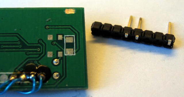
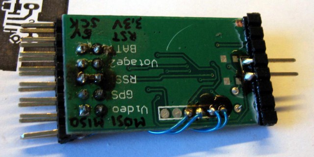
Potrzebna jest nowa listwa kątowa goldpinów. Trzeba usunąć niepotrzebne piny, a pozostałe przyciąć do krawędzi plastiku jak na zdjęciu:
Najlepiej teraz przykleić plastik do płytki z pinami w odpowiedniej pozycji (nad padami do przylutowania), najprościej na SuperGlue/CA:
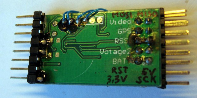
Po kilku sekundach gdy wszystko już trzyma się kupy można spokojnie przylutować piny do padów:
W tej chwili jeden z pinów jest podłączony z nowym wejściem, drugi można łatwo podłączyć do masy gdzieś obok.
Można założyć termokurczkę i to wszystko.
ale…
Nie przepadam za robieniem tych samych rzeczy po kilka razy, więc od razu dodałem kolejne piny dla przyszłych zastosowań (dobrze byłoby do nich podłączyć kiedyś i2c i tx z rs-a) 🙂

Hi Majek!
Thanks for your article and schematics!
I figure you have some understanding on how this G-OSD works… Perhaps you could help me with my problem: my video goes BW when I connect my camera to OSD. It does flicker BW/Color but stays BW most of the time…
The camera alone does give a clean color image. Any ideas what I could do?
Thanks for your time,
Dmitry.
Hello Dmitry
Did you checked your connections for ground loop? If you connect ground in wrong way, a weird things happen (up to video signal loss). G-OSD itself shouldn’t influence colour – in fact it makes modifications to video signal only where characters are – other parts of signal is untouched. Try to rewire connections and check if it helps. I had similar problem (poor colour and sometimes synchronization lost) and I solved it by disconnecting redundant ground wires.
If you power video from the same battery as motor, I’m pretty sure you have at least two grounds connected to the osd – one on video side, second from battery and it forms a loop with ground for powering video TX. Leave only one ground connected to OSD and it should help.
Or try to test this with separate battery for video equipment.
Hey Majek!
Thanks for your reply!
I was thinking about thiese ground issues as-well, but the strange thing is that I have a second G-OSDII (bought both at once -> should be the same batch), that works just fine with the same cable!
Ok, but I get your point… I will try to re-solder the elements on the board – perhaps some cold-joint issue…
(By the way, I accidentally broke a Quartz leg – do you know the specs exactly? Apart from it being 24Mhz)
I don’t think that it could be cold-joint. Your signal is weaker, so maybe R11/C8 have bad values. Or there is some short-circuit somewhere.
Do you have proper OSD graphics?
Regarding quartz – any 24MHz should work but I think that there will be hard to buy in such small package – standard HC49 should be no problem.
Hey, perhaps we should switch to email conversation, you should have mine, since it is necessary to enter prior sending this reply…
Today I got the same effect with the second OSD :(.
I got an impression, that new heat-shrink might be the reason for that (well, not the shrink itself, but the process of putting it ;)… Or that it is physically rather close to my VTx…
I think OSD text is clean, it is hard to tell though…
Will check the R11/C8 chain and short circuits…
Thanks again,
Dmitry.
Hello,
I was wondering if you still have the Eagle files for this OSD? I wanted to play around a bit with it but still learning eagle PCB.
I have only schematic: https://majek.sh/modele/g-osd.sch
I hope it helps 🙂
How we can read and show the value for this #3 input?